Digital FM broadcast
transmitter
The SDR7020 is a Pluto clone with a Zynq 7020 and an AD9363, from 70 MHz to 6 GHz. With the FPGA design of Willem, PE1PCF, it becomes a complete FM transmitter: analogue MPX in, FM out, without a PC in the signal path. digiWUFFUM, the Windows software of PE1PzN, is the program that goes with it: control the transmitter and measure what really goes on air. The program itself is in Dutch.
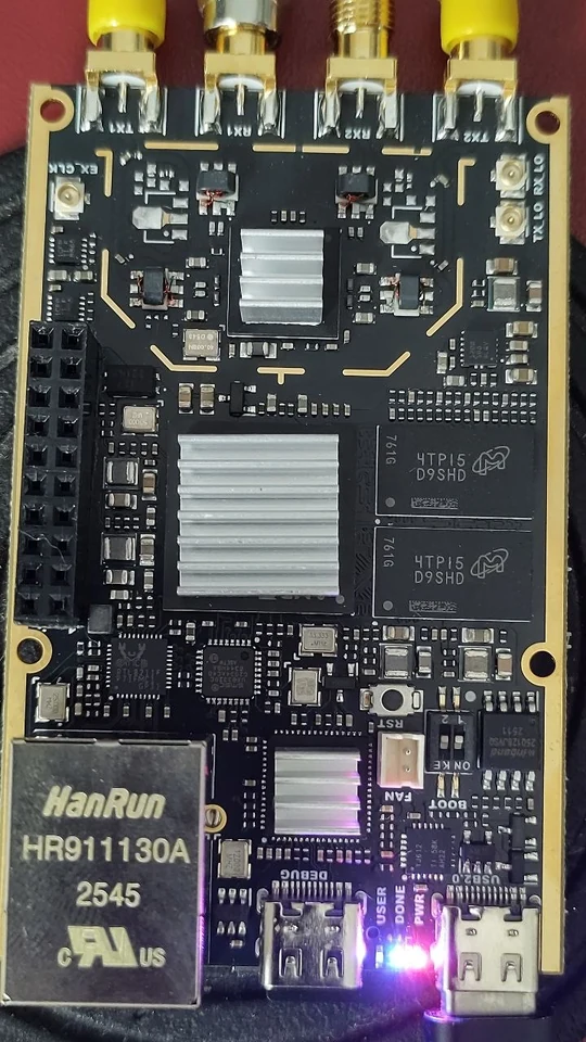

The sound does not go through the PC. Your stereo encoder delivers an ordinary analogue MPX signal, a small I2S board close to the SDR7020 converts it, and the FPGA turns it into FM modulation. The PC only sets and measures. If the PC drops out, the SDR7020 switches the transmitter off by itself after five seconds.
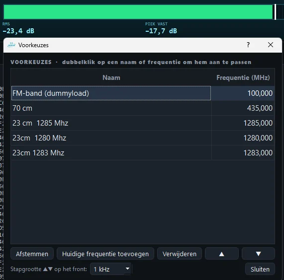
- Control the transmitter. Frequency, power, presets, on and off, as on a rack transmitter.
- Measure what goes out. Deviation, pilot, RDS injection, MPX power to BS.412, channel separation and the phase of the 38 kHz.
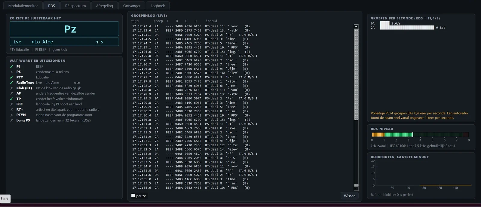
- Read RDS completely. PS, RadioText, RT+, clock, PTYN, Long PS, AF list and the groups per second.
- Alignment. Null the image and carrier leakage, automatically and stored per frequency.
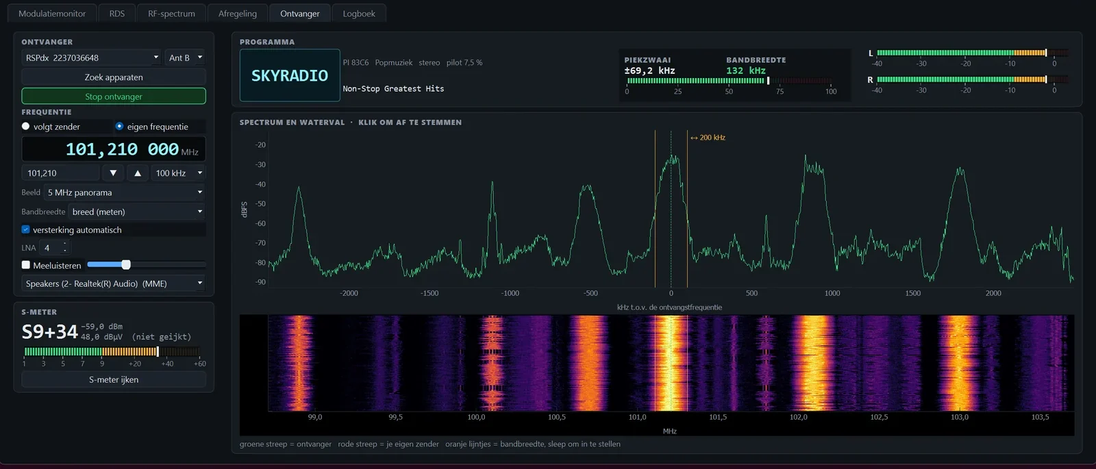
- A second receiver. Spectrum, waterfall and S-meter to look at other stations. Listening in is possible too, via a second SDR (RSPdx).
- Transmit and receive at the same time (from 3.0). With a DAC board added you listen without delay to an FM station from 70 MHz to 6 GHz, while you transmit yourself.
Version 3.2 replaces 3.1. Program and SD card are both new:
- Noise reduction in the receiver. A slider from 0 to 10: first stereo gradually goes to mono (that is where most of the noise is), then the treble goes down step by step. All by hand, no automatic.
- No more clicks. When retuning, switching tabs and with mono or 75 µs, the DAC sound now closes and opens softly.
- Alignment always right. The alignment per frequency is now always sent to the 7020, also after a restart of the 7020.
Version 3.1 replaced 3.0:
- Works on every SDR7020. On some boards no MPX came through with 3.0 or the DAC stayed silent. The cause was in the start-up of the FPGA and has been fixed.
- Let the 7020 be found. Next to the IP address is the Zoek (search) button: digiWUFFUM finds the 7020 via USB or on your network and fills in the address. It does not log in anywhere.
- Home network 192.168.2.x (for example with KPN) now works as well. That clashed with the USB address of the 7020; the card solves it by itself.
- The transmitter stays on. It sometimes switched off by itself when the program was briefly busy. That no longer happens.
Since version 3.0 two things stand out:
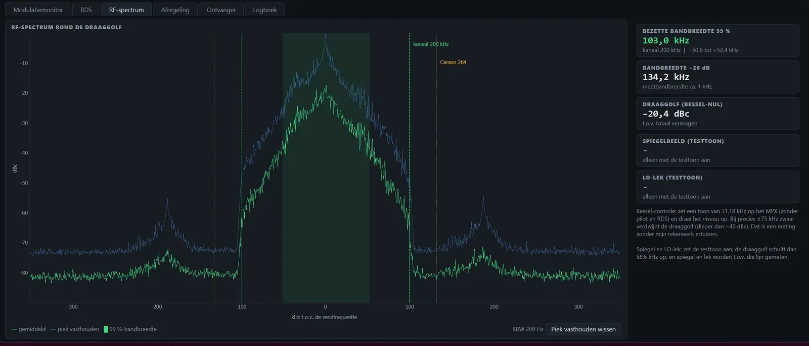
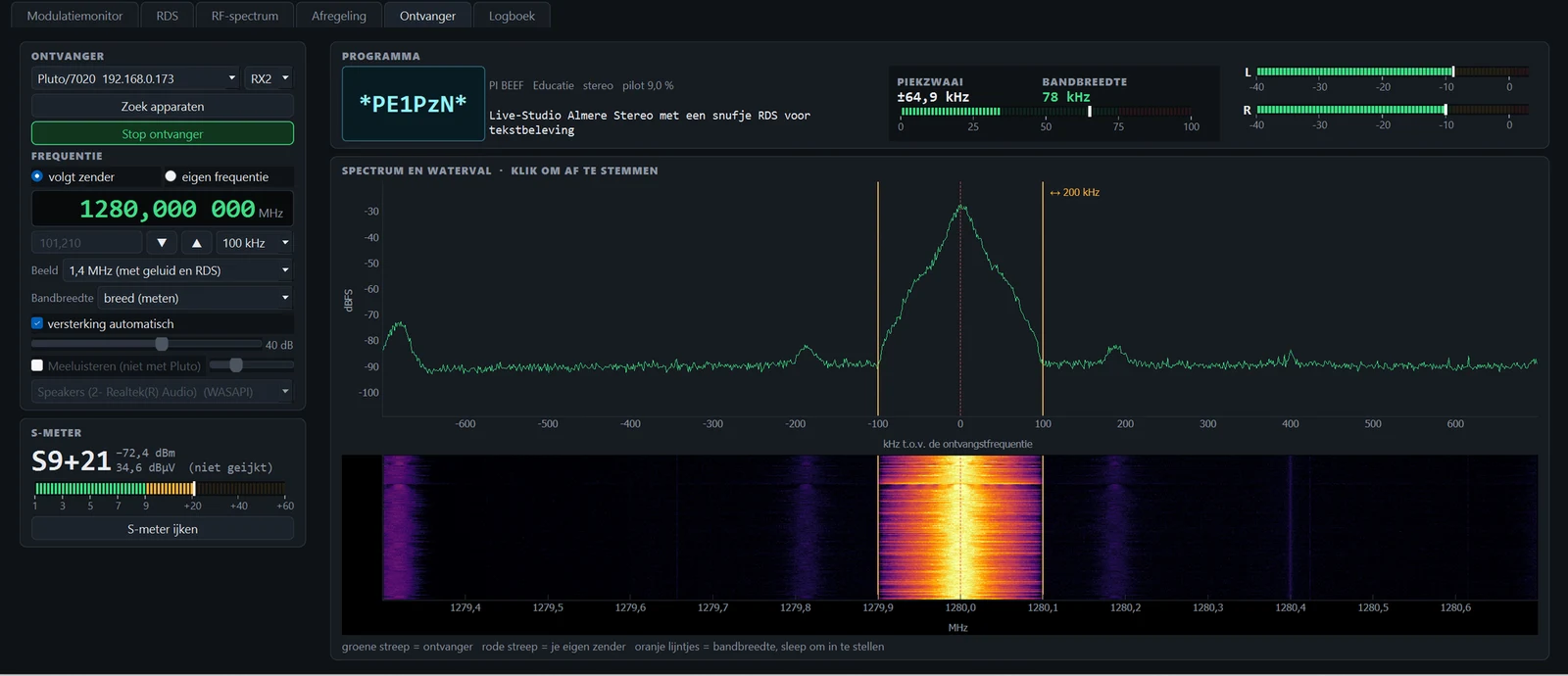
- A cleaner signal. The whole FM chain in the FPGA has been rebuilt. Next to the channel it is quiet: no more humps beside the carrier, and the channel filter is steep. A 200 kHz channel is now really 200 kHz wide.
- Transmit and receive at the same time. The FPGA now also contains an FM receiver: stereo, de-emphasis 50 µs and a squelch. The sound goes straight to a DAC board on the GPIO port, as with digiNICAM. There is no PC in between, so no delay either. You choose RX1 or RX2 and any frequency from 70 MHz to 6 GHz.
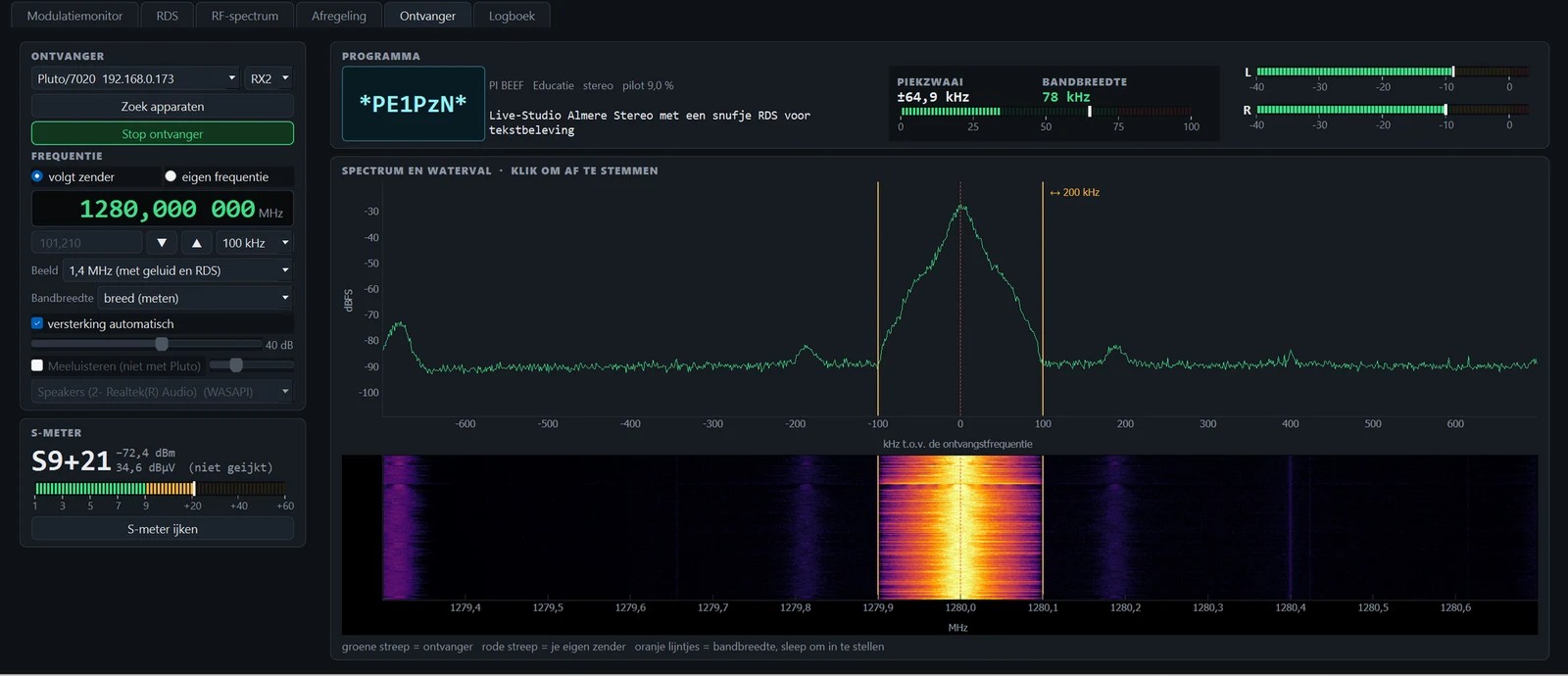
- Tuning per digit. Put the mouse on a digit of the frequency and turn the wheel: only that digit changes, from 1 Hz to 1 GHz. That works for the transmitter and the receiver.
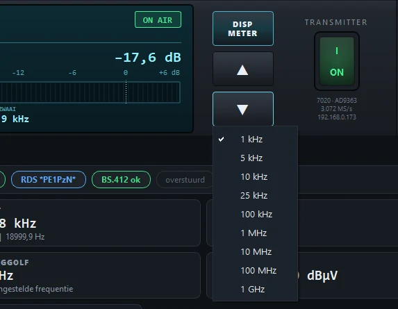
- Choose the step size. Right mouse button on ▲ or ▼: from 1 kHz to 1 GHz.
- Panorama without ghost stations. Looking wide (5, 9 or 20 MHz) now uses a scan along the band. That works when the sound from the DAC is off; if you listen, the view stays 2 MHz wide.
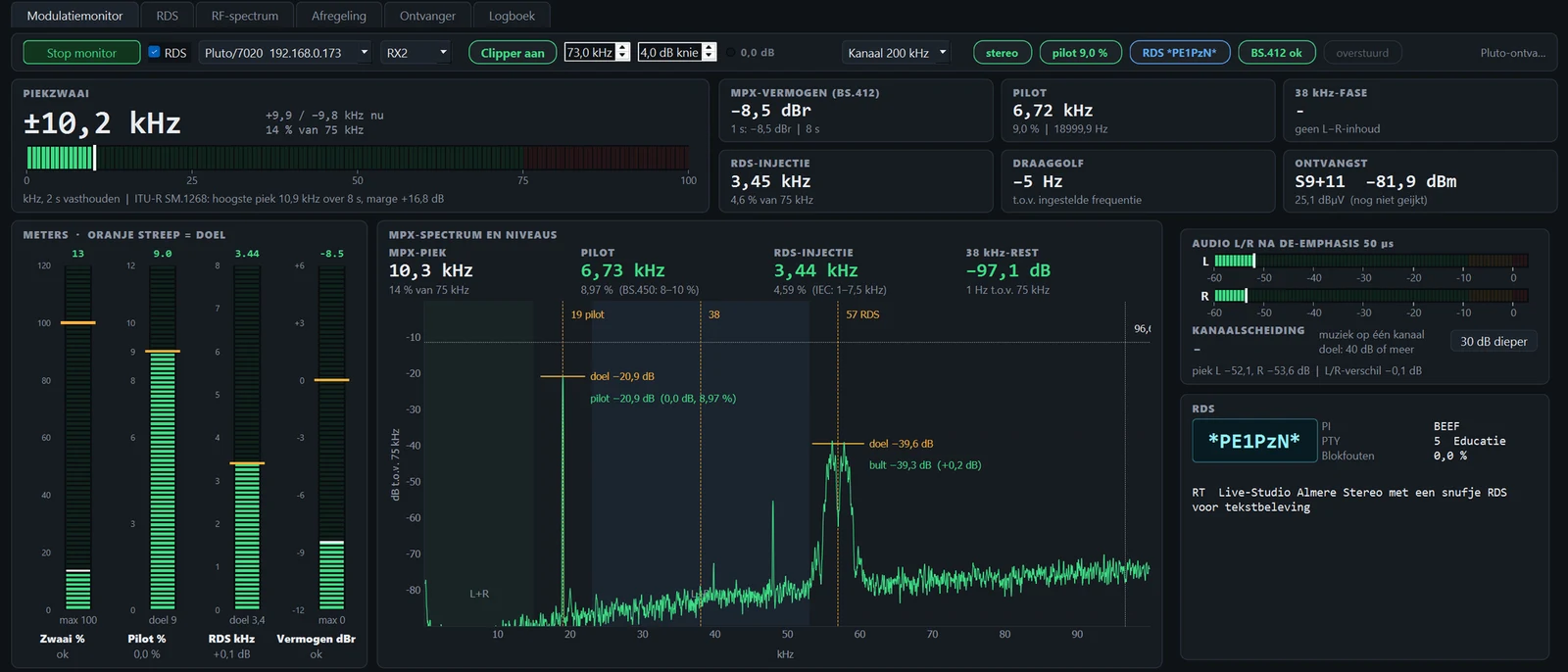
You measure your own transmitter with the SDR7020 itself, via the second receive input, or with an RSPdx. The peak deviation follows ITU-R SM.1268, the MPX power BS.412 over sixty seconds. Besides that the pilot and its exact frequency, the RDS injection, and the error of the 38 kHz subcarrier relative to twice the pilot: that almost entirely determines how good your channel separation is.
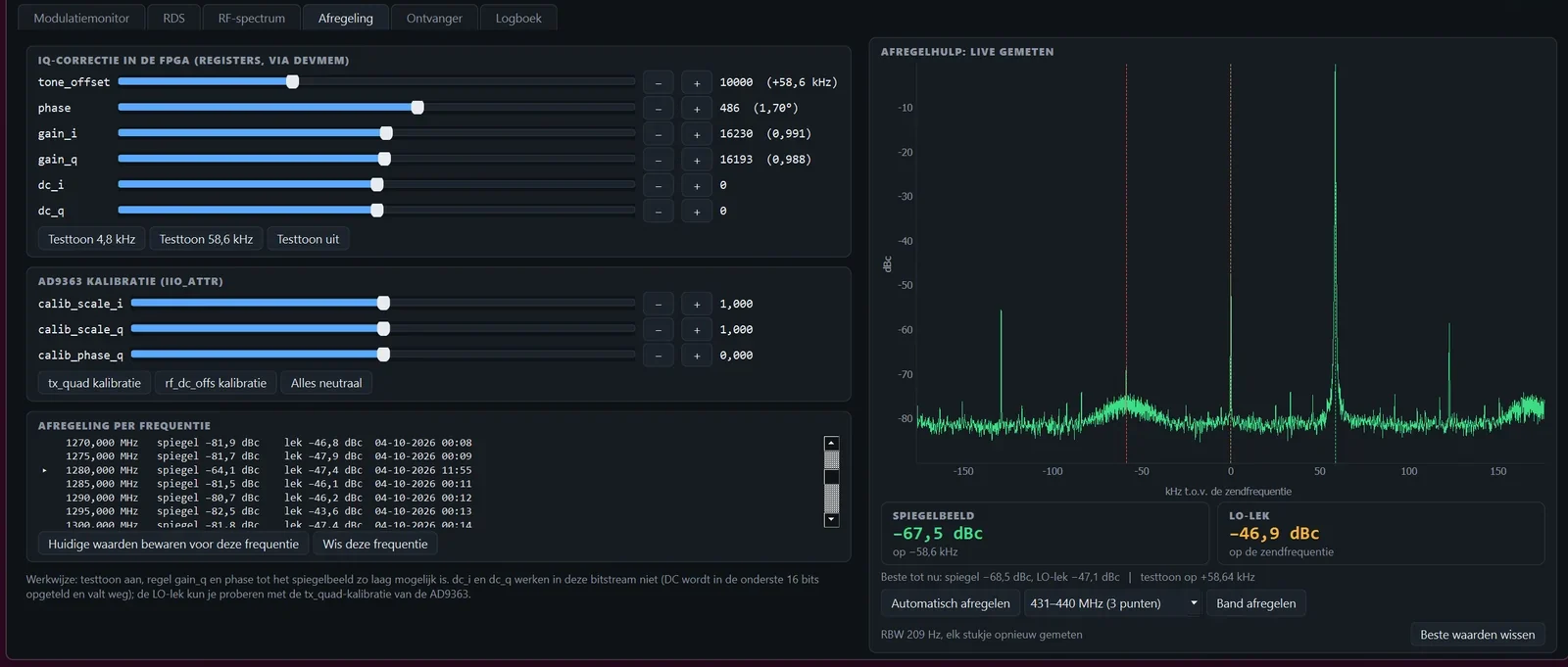
An IQ transmitter always makes a little image and a little carrier leakage, and how much differs per frequency. With the test tone on, digiWUFFUM measures both and finds the best setting itself. The result is stored per frequency; with Band afregelen (align band) you go through a whole band in steps of 5 MHz. On 23 cm that reaches an image rejection of around 80 dB.
The basis is the design of Willem, PE1PCF (on GitHub). Meanwhile I have improved and added some nice things.
Card 3.2, for transmitting and receiving:
- MPX clipper right before the modulator, with a soft knee and a hard limit. What sticks out above it does not go on air.
- Channel filter switchable: wide (flat to 150 kHz), 200 kHz or 190 kHz. Steep: at 200 kHz everything from 104 kHz beside the carrier is more than 100 dB down.
- IQ correction with limiting, and carrier correction (dc_i, dc_q), adjustable per frequency.
- FM receiver from 70 MHz to 6 GHz on RX1 or RX2: channel filter, stereo decoder, de-emphasis 50 or 75 µs and a squelch, with the sound straight to the DAC board.
Card 2.6, my changes:
- No clicks (new in 2.6): the samples now cross safely to the clock of the AD9363. Before, it occasionally got a half old, half new sample, and that gave single spikes up to a few MHz beside the carrier.
- MPX clipper right before the modulator, with a soft knee and a hard limit. What sticks out above it does not go on air.
- Channel filter switchable: wide (flat to 150 kHz), 200 kHz or 190 kHz.
- I/Q filter flat to 150 kHz, was -6 dB at 100 kHz and so cost stereo and RDS.
- IQ correction with limiting, and the carrier correction (dc_i, dc_q) that did nothing in the original.

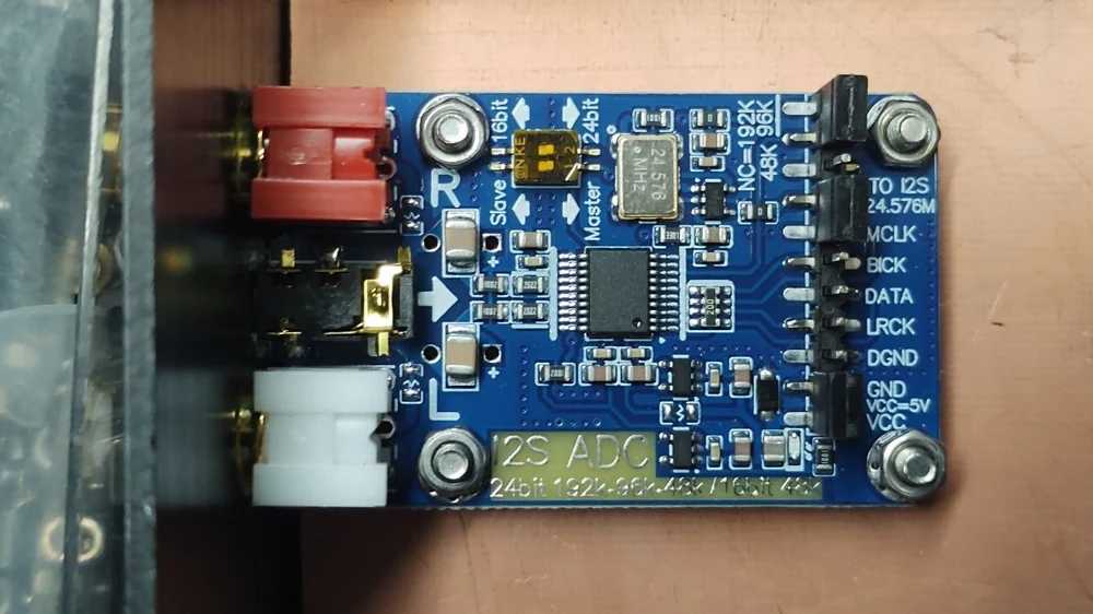
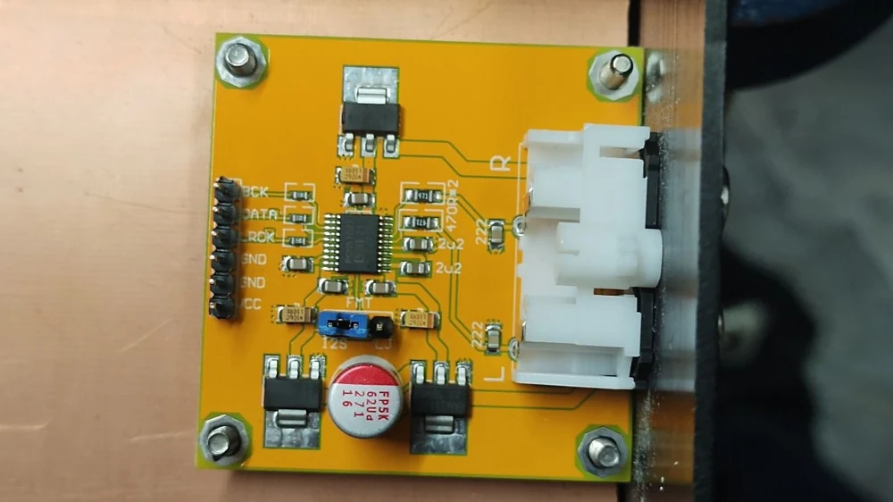
The ADC board: I2S ADC Audio Capture Card Module, 24 bit, 192 kHz, Master/Slave · for example at Amazon
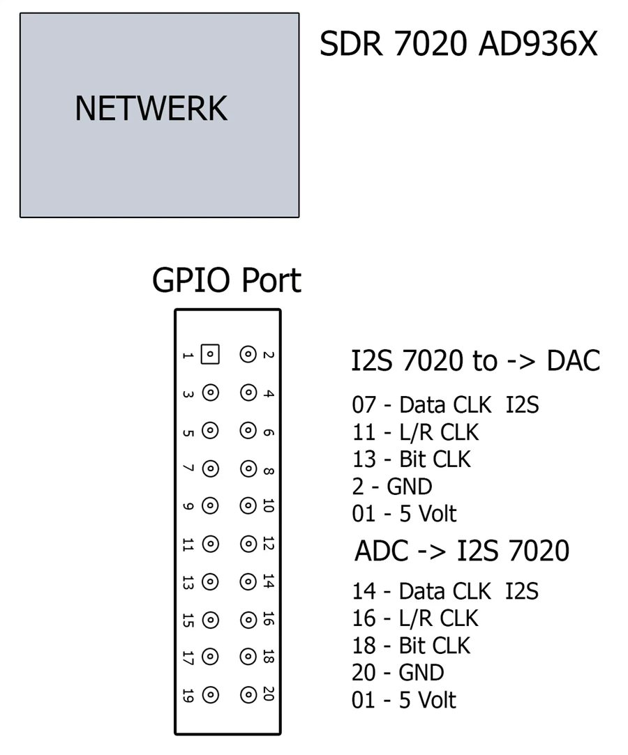
ADC BOARD TO THE GPIO PORT
DAC BOARD TO THE GPIO PORT (3.x)
NOTE
ADC board ---[ 1 kΩ ]---+---> GPIO pin 14 / 16 / 18
                        |
                   [ 1.2 kΩ ]
                        |
                      ground
3.3 V × 1.2 / 2.2 = 1.8 V. No divider to the DAC board (pins 7, 11, 13): those pins are on the 3.3 V bank and the PCM5102A itself also runs at 3.3 V.
Update 19 October 2026 (evening): digiWUFFUM 3.2. Replaces 3.1. Noise reduction in the receiver, no more clicks in the DAC sound, and the alignment per frequency is always applied. Works on every SDR7020, with the Zoek button and the fix for home networks with 192.168.2.x. Always update program and SD card together: program 3.2 belongs with card 3.2. Version 2.6 stays available below.
The program is not signed with a certificate; that costs a few hundred euros per year. So Windows does not know the maker and warns at the first start with Windows protected your PC. Click More info and then Run anyway.
If you want to be sure you have exactly my file: the SHA-256 checksum is shown with every download. In PowerShell you check it with Get-FileHash filename.zip.
WHAT YOU NEED
FIRST TIME
Thanks
Who made what. The FPGA design with the FM modulator is by Willem, PE1PCF. The Windows software digiWUFFUM, the clipper and the channel filter in the FPGA (card 2.3 and later) and the manual are by PE1PzN.
Thanks to Willem, PE1PCF, for the enormous amount of time he put into the FPGA design that all of this runs on.