Digital NICAM-728
directly on 70 MHz to 6 GHz
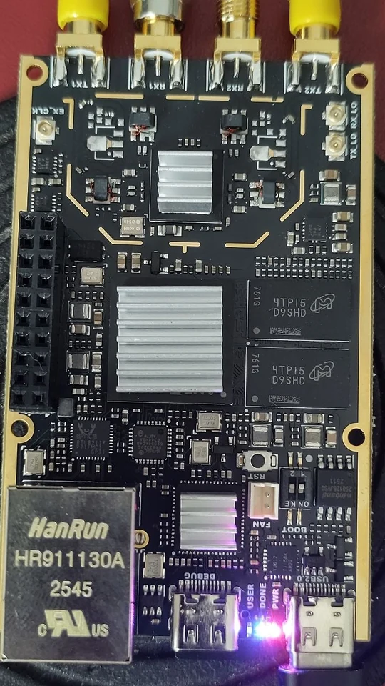
digiNICAM turns the SDR7020 (Zynq 7020 + AD9363 or AD9361, the boards are otherwise the same) into a NICAM-728 stereo transmitter that transmits directly on the frequency you choose, from 70 MHz to 6 GHz, without mixer or intermediate frequency. With a receiver too. The FPGA design is entirely home-built. And it contains an own, narrower system, PzN, that achieves the same with about 13 dB less transmit power.
What is PzN? An own digital sound system by PE1PzN for the SDR7020: narrower than NICAM and more robust, with error correction. You choose two things separately: the bit rate (80, 112, 192 or 256 kbit/s per channel) and the modulation: QPSK (narrow, linear power amplifier) or 4GFSK, also called DX (the power amplifier may be fully driven, as with FM). PzN 256 exists only with QPSK, and sounds as good as NICAM.
Which codec? The PzN codec, an own design: the sound is split into 32 frequency bands and the bits go where the sound is. It delays only 3 ms and runs entirely in the FPGA. It is not an existing codec like AAC or Opus.
NICAM-728 was designed in the late eighties for ordinary analogue TV, which was transmitted with AM. In the nineties almost every TV transmitter got a digital stereo sound carrier with it, next to the picture and the ordinary FM sound carrier.
Radio amateurs use NICAM with FM-ATV, as a subcarrier on 6.552 MHz in the baseband, together with the picture. That works, but FM-ATV is wide: a channel of 18 to 27 MHz. The sound then gets all the noise of that whole wide channel.
And the narrower you transmit, the further you get. The noise in a receiver grows with the bandwidth, and every 6 dB less noise is twice the distance in free space. That is why narrowband transmitters with SSB or CW get so far with a few watts. If you transmit NICAM directly as its own 728 kHz signal, instead of inside an FM-ATV channel, that already makes a big difference:
BANDWIDTH AND GAIN
WHAT THAT MEANS
Only part of the PzN gain comes from the narrower bandwidth. The rest comes from the error correction: NICAM only has a parity bit, PzN really corrects the errors. How that works is explained further down under PzN.
The transmitter runs entirely in the FPGA. The sound comes in via I2S, is converted to 32 kHz in the FPGA and coded according to ETS 300 163: J.17 pre-emphasis, 14 to 10 bits per block of one millisecond, parity, interleaving, scrambling, DQPSK with RRC filter. A NICAM decoder from the nineties plays it without problems.
- System I (728 kHz wide) and B/G (510 kHz), and inverting the spectrum for those who mix with the LO above the signal.
- Station ID in the AD bits, the method of PE1OBW and PE1MUD for the MSP34x5G: your own call appears on the receiver.
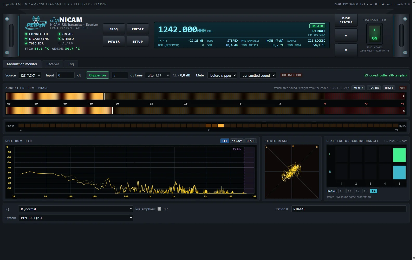
- I2S input from an ADC board (192 kHz) with a sample rate converter in the FPGA, noise and distortion around -85 dB. Or a fixed test tone: left 1 kHz, right 400 Hz.
- Soft audio clipper in the FPGA, your choice before or after the J.17 pre-emphasis. Before J.17 it clips the programme itself at 0 on the meter; after J.17 it only protects the 14 bits against the high tones.
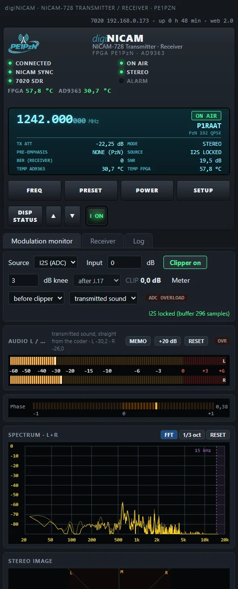
- Meters on the sound as the transmitter codes it, straight from the SDR7020: PPM with the Digital Baseband scale (0 = -12 dBFS), before and after the clipper, phase, spectrum, goniometer and coding range.
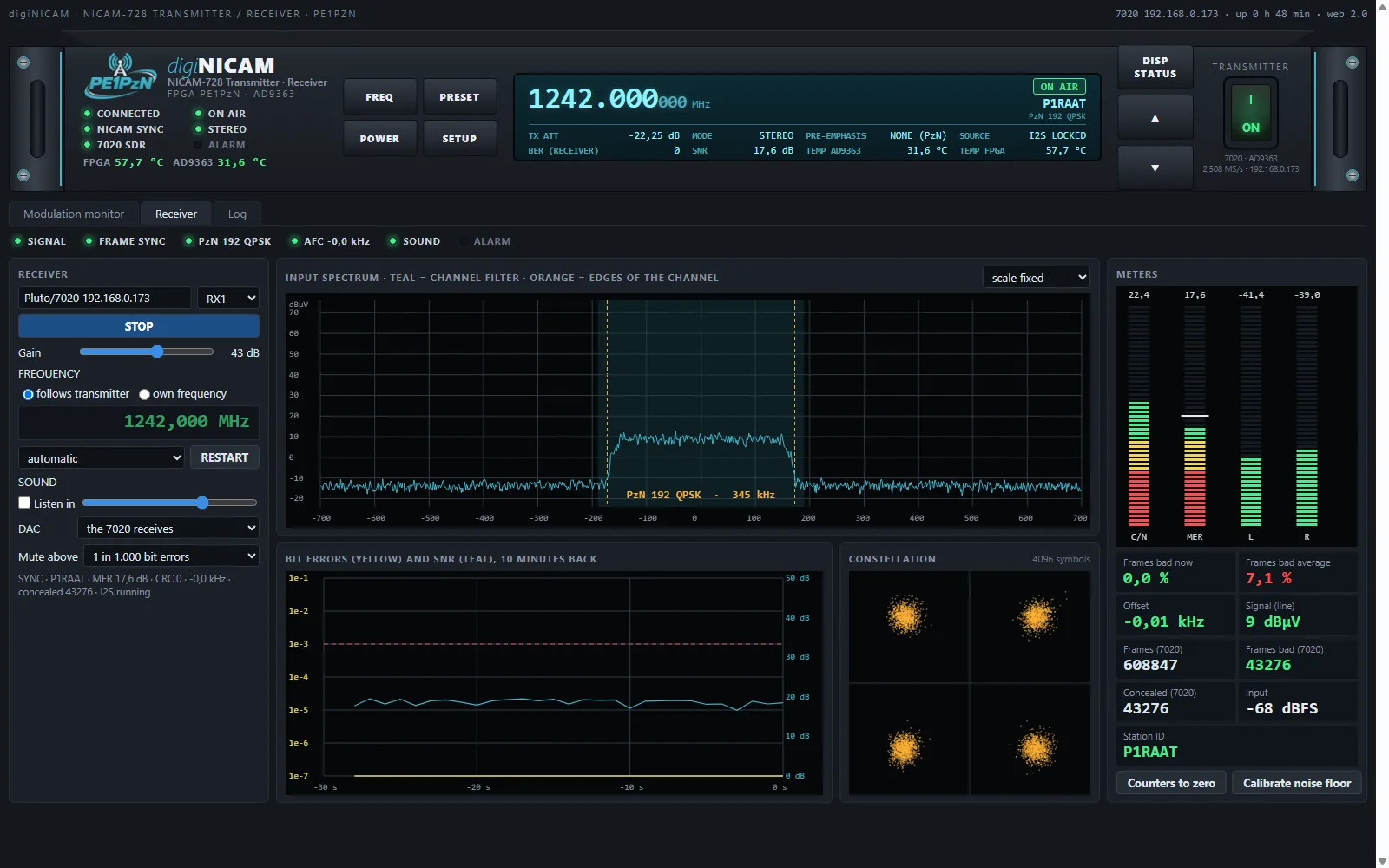
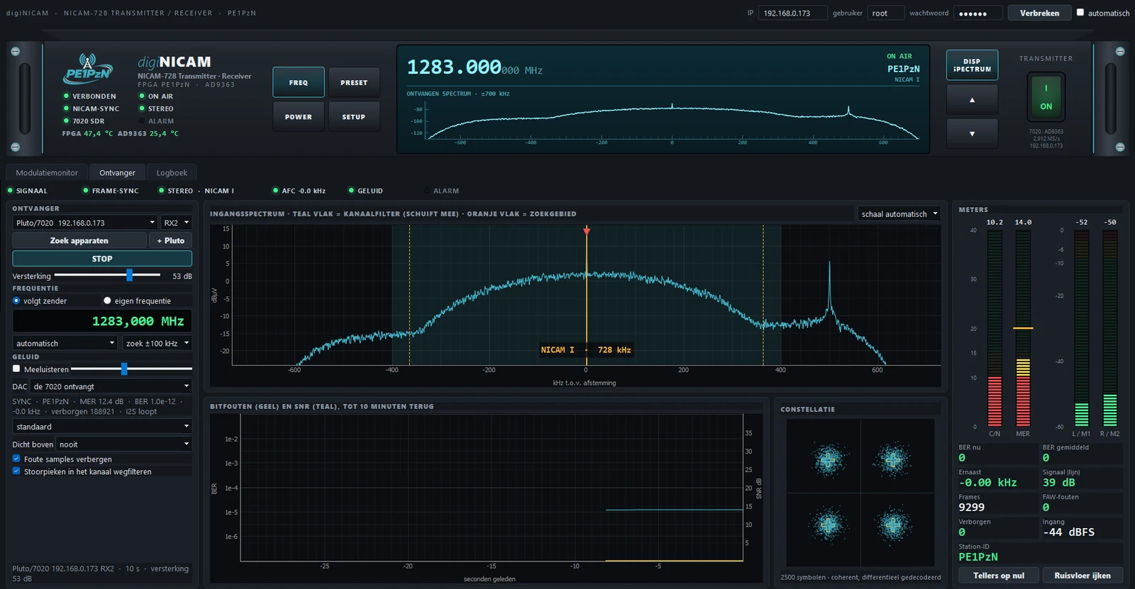
Reception uses RX1 or RX2 of the SDR7020 itself. The receiver searches for the signal up to 200 kHz beside the tuning and recognises by itself which system comes in: NICAM I or B/G, normal or inverted, or one of the PzN modes. If your own transmitter is on, it tries that system first, and after switching it locks within a few seconds. You see the constellation, the spectrum in dBµV from the noise floor, the C/N, the MER, the bit errors over ten minutes and the station ID. A fixed interference spike in the middle of the channel is removed automatically, and with too many errors the sound mutes softly, as with the MSP 3400.
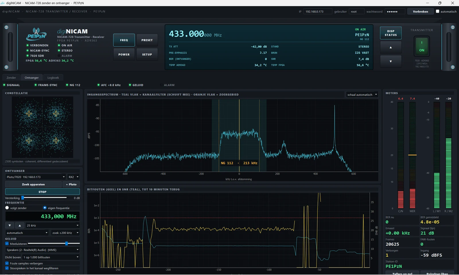
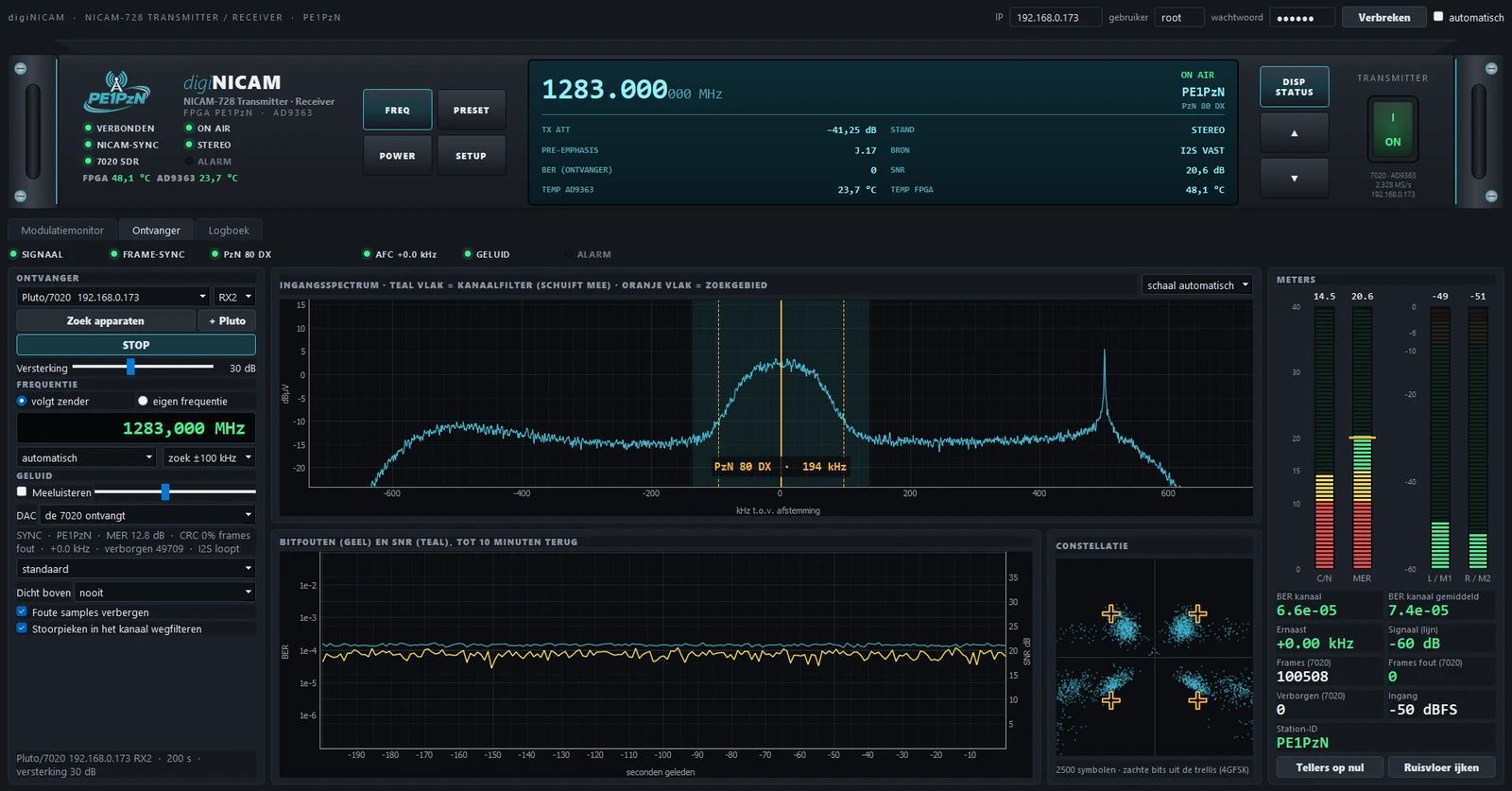
NICAM puts all its bits into sound quality and keeps nothing for error correction. PzN does it the other way round: a smarter codec needs only about a third of the bits at PzN 112, and the space that is freed goes to error correction and a narrower channel. PzN 256 sounds as good as NICAM, in less bandwidth. The codec, the PzN codec, splits the sound every millisecond into 32 frequency bands and gives the bits to the bands where the sound is: the NICAM idea of one scale factor per millisecond, but per band.
THE MODES
HOW
The PzN codec is an own transform codec, from the same family as AAC, ATRAC and Opus, but built on the NICAM idea. NICAM gives the whole sound one scale factor every millisecond. The PzN codec does that per frequency band, and that is why it needs only about a third of the bits at PzN 112.
- Splitting. Every millisecond (32 samples) an MDCT splits the sound into 32 bands of 500 Hz.
- Grouping. The bands are in 8 scale bands: narrow at the low tones, wide at the high ones, as the ear hears.
- How loud. Per scale band an exponent: how loud that band is at this moment, in steps of 3 dB.
- Sharing the bits. Loud bands get many bits, quiet ones few or none. The receiver calculates the same allocation itself from the exponents; so that costs no bits.
- Protecting. The exponents and the top bits of the low bands (up to 3 kHz, where you hear an error first) are under a CRC. If something goes wrong, it repeats the previous block, 6 dB softer each time: no crackling.
Why an own codec? Existing codecs like Opus or AAC get more quality out of fewer bits, but they are made for computers and phones: they need a processor with an operating system and delay the sound by 20 ms or more. The PzN codec is so simple that it fits entirely in the FPGA. It delays about 3 ms, and the sound does not have to pass through a PC or the operating system of the SDR7020. That suits NICAM: direct, robust, and without a delay you hear when working duplex.
THE CODEC
DELAY
Two steps. A digital transmitter does two things one after the other. First the codec makes the sound small: from many bits to fewer bits. Then the modulation puts those bits on the carrier. The codec decides how good it sounds. The modulation decides how wide the signal is and how far it gets.
NICAM-728. The codec of the old TV stereo. It cuts every sample from 14 to 10 bits and remembers per block how loud it was. Simple and fast. It has almost no error correction: only a check bit. One wrong bit is quickly heard as a click.
PzN. An own codec by PE1PzN. It divides the sound into 32 frequency bands, just like MP3. Each band gets only as many bits as your ear needs. That way it compresses much more than NICAM, but with very little delay: the codec about 3 ms, the whole system about 5 ms. It has real error correction (Viterbi). That repairs errors before you hear them. That is why PzN still works with a much weaker signal. PzN 112 means: 112 kbit/s per channel, so 224 kbit/s stereo.
| Stereo, 32 kHz | Bit rate | Smaller |
|---|---|---|
| no compression (16 bit) | 1024 kbit/s | |
| NICAM | 640 kbit/s | 1.4 times |
| PzN 256 | 512 kbit/s | 2 times |
| PzN 192 | 384 kbit/s | about 2.7 times |
| PzN 112 | 224 kbit/s | about 4.5 times |
| PzN 80 | 160 kbit/s | about 6.4 times |
Note: this is data compression, not dynamic compression. Loud stays loud and quiet stays quiet. Only the clipper flattens the peaks at -12 dBFS.
DQPSK and QPSK (NICAM and PzN QPSK). The transmitter jumps between four phases. To keep the signal narrow, it goes through a filter. Because of that the power keeps going up and down. The power amplifier has to follow that neatly: it must be linear. So it may not be fully driven: about 15 W instead of 150 W.
4GFSK (PzN DX). The transmitter jumps between four frequencies, softly rounded (Gaussian). The power always stays the same, just like with FM. So the power amplifier may be fully driven, as with FM. There are no shoulders as with DQPSK and QPSK. That is about 10 dB more. FSK does need some 3.5 dB more signal. So net you gain about 6.5 dB. That is more than twice as far.
What are the shoulders? If you look at a QPSK signal with a spectrum analyser, you see a flat hump: the channel. If you drive the power amplifier too hard, two lower edges grow left and right of the hump. Those are the shoulders. They arise because the power amplifier no longer neatly follows the up and down of the power. Mixing products are then added. The lower the shoulders, the cleaner your transmitter. Driving less hard makes them lower. That does cost power.
With 4GFSK you hardly have that problem. The power does not go up and down, so the power amplifier makes no shoulders. The skirts of an FSK signal come from the shaping itself. With BT 0.5 those skirts are steeper than with BT 0.7.
What is BT? A measure of how softly the transmitter slides from one frequency to the other. High BT: fast and sharp, wider signal. Low BT: soft, narrower signal with steep skirts, but the symbols run into each other more and the receiver has to work harder. GSM uses 0.3, Bluetooth 0.5. PzN DX uses 0.5: narrow, and it costs only 0.2 to 0.3 dB sensitivity.
A band-pass filter after the power amplifier stops the harmonics (2x, 3x the frequency). It does not stop the shoulders right next to the channel. You have to keep those clean at the source.
| Mode | Modulation | Width (99 %) | Error correction | Power amplifier |
|---|---|---|---|---|
| NICAM I | DQPSK | 700 kHz | check bit | linear |
| NICAM B/G | DQPSK | 500 kHz | check bit | linear |
| PzN 256 | QPSK | 450 kHz | Viterbi | linear |
| PzN 192 | QPSK | 345 kHz | Viterbi | linear |
| PzN 112 | QPSK | 213 kHz | Viterbi | linear |
| PzN 80 | QPSK | 160 kHz | Viterbi | linear |
| PzN 192 DX | 4GFSK | 473 kHz | Viterbi | fully driven (as FM) |
| PzN 112 DX | 4GFSK | 292 kHz | Viterbi | fully driven (as FM) |
| PzN 80 DX | 4GFSK | 194 kHz | Viterbi | fully driven (as FM) |
Which bit rate? The more bits, the better the sound, but the wider the signal.
| Mode | QPSK | 4GFSK | Sound |
|---|---|---|---|
| NICAM I / B/G | 700 / 500 kHz | the reference | |
| PzN 256 | 450 kHz | - | As good as NICAM, in less bandwidth. |
| PzN 192 | 345 kHz | 473 kHz | Fine. Very slightly affected. |
| PzN 112 | 213 kHz | 292 kHz | Fine. Critical listeners hear a very slight artefact. |
| PzN 80 | 160 kHz | 194 kHz | Everyone hears that it is less. Nice for trying a difficult path, but not for the quality. Still cleaner than noisy FM. |
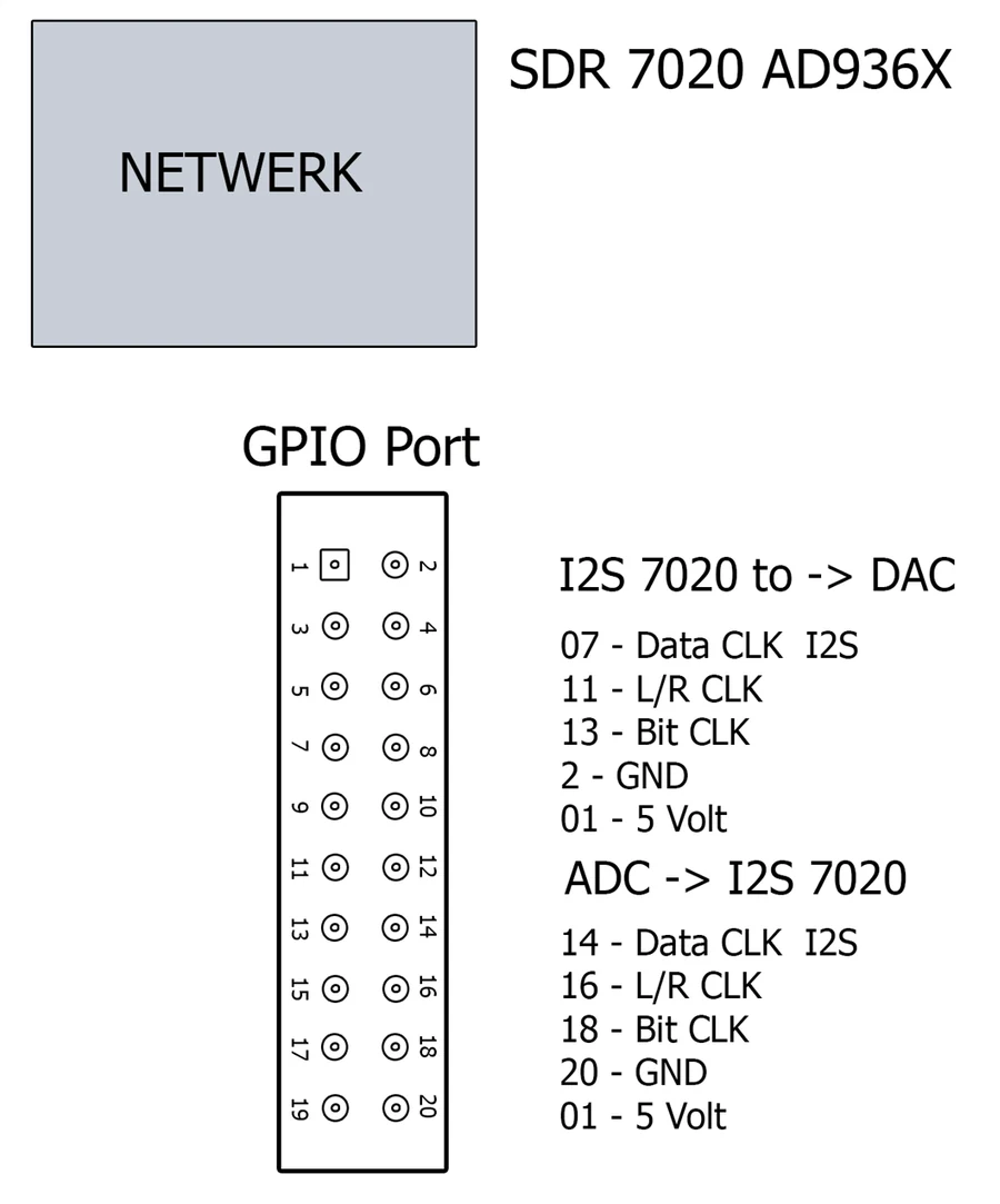
The SD card also has a receiver in the FPGA, for NICAM and PzN. The sound then goes straight via I2S to a DAC board, without a PC in between and with little delay: handy when you work duplex with the transmitter on one band and the receiver on another. That works for NICAM and for all PzN modes, with QPSK and with 4GFSK (DX).
Transmitter and receiver share one sample rate in the AD9363. With the transmitter off, the receiver chooses the system: it follows whatever comes in, NICAM or PzN. When it transmits, the transmitter decides, and the receiver can only receive the same system. So duplex works when both sides use the same system, each on its own frequency.
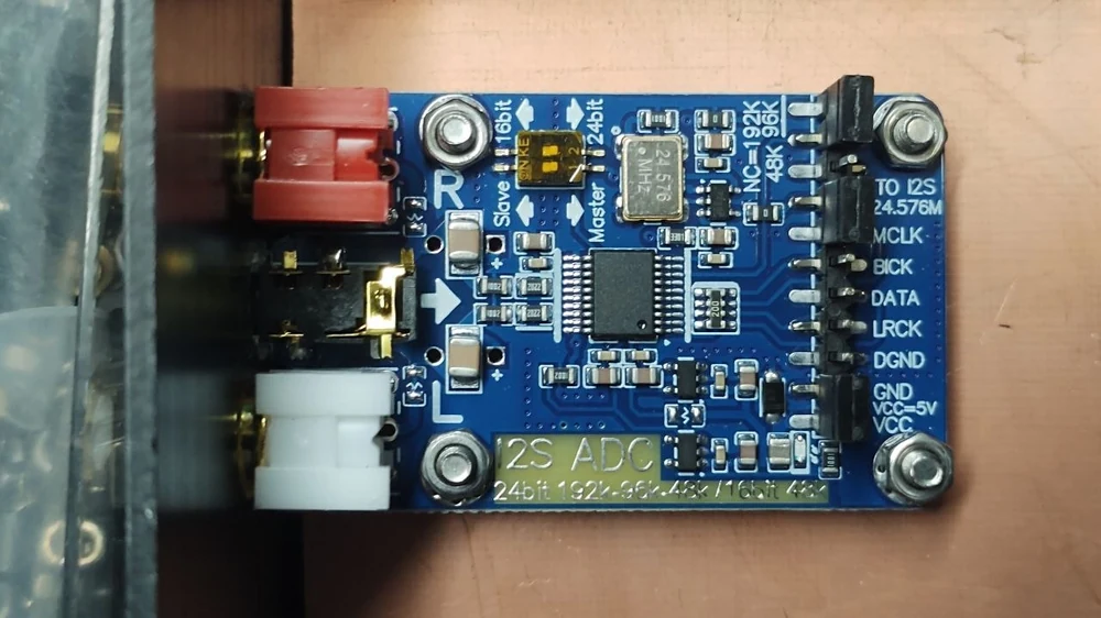
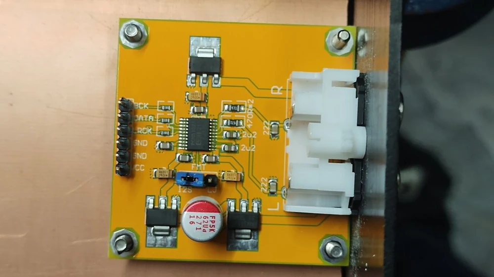
The ADC board: I2S ADC Audio Capture Card Module, 24 bit, 192 kHz, Master/Slave · for example at Amazon
ADC BOARD (SOUND IN)
DAC BOARD (SOUND OUT, PCM5102A)
ADC board ---[ 1 kΩ ]---+---> GPIO pin 14 / 16 / 18
                        |
                   [ 1.2 kΩ ]
                        |
                      ground
3.3 V × 1.2 / 2.2 = 1.8 V. No divider to the DAC board (pins 7, 11, 13): those pins are on the 3.3 V bank and the PCM5102A itself also runs at 3.3 V.
Update 3 November 2026: digiNICAM V2.03. Everything is on the SD card, including your settings. Insert the card, switch on, and after about a minute the web page is ready. Nothing is written to or removed from the 7020's memory: take the card out, and the 7020 is as it was. The IP address stays the same.
Opruimen.bat (clean up). Are there still files from an older version or from other software (such as the ATV-RX of fm-atv.nl) in the 7020's memory? Opruimen.bat removes them, including the settings. After that it is as it was when bought. The IP address stays the same.
The SHA-256 checksum is shown with the download. In PowerShell you check it with Get-FileHash filename.zip.
WHAT YOU NEED
FIRST TIME
Questions
Everything is explained step by step in the manual (pdf). Something not right, or a question about PzN? Let me know, and I will look into it.